Konsep 20+ PWM Inverter Schematic
Poin pembahasan Konsep 20+ PWM Inverter Schematic adalah :
Konsep 20+ PWM Inverter Schematic. Berikut Penjelasan lengkap tentang fungsi komponen-komponen skema mesin las dari yang aktif hingga pasif, prinsip cara kerjanya serta simbol yang wajib difahami. Perhatikan komponen skema mesin las jenis resistor berikut yang dilengkapi dengan gambar. Simak ulasan terkait skema mesin las dengan artikel Konsep 20+ PWM Inverter Schematic berikut ini

Schematic structure of a voltage PWM inverter Download Sumber : www.researchgate.net

shows the complete circuit diagram of the PWM inverter Sumber : www.researchgate.net

sinewave inverter circuit SG3524 PWM SL technological Sumber : sltech360.blogspot.com

SG3524 PWM INVERTER CIRCUIT Many circuits Sumber : manycircuits.blogspot.com
Inverter sg3524, Ic SG3524N, Irfp250 inverter circuit,

Single phase PWM inverter Download Scientific Diagram Sumber : www.researchgate.net

250 to 5000 Watts PWM DC AC 220V Power Inverter Sumber : www.instructables.com

SG3525 Pure Sinewave Inverter Circuit Sumber : www.homemade-circuits.com

250W PWM inverter circuit SG3524 ELECTRONICSMASTER Sumber : electronicsmaster.weebly.com

PWM inverter circuit based on SG3524 12V input 220V Sumber : www.circuitstoday.com

PWM Inverter Circuit Sumber : theorycircuit.com

Inverter 5000 Watt PWM Circuit Schematic Electronics Sumber : circuitschematicelectronics.blogspot.com

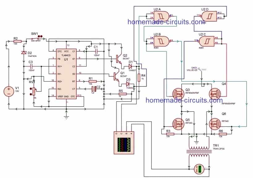
PWM Inverter Using IC TL494 Circuit Homemade Circuit Sumber : www.homemade-circuits.com

PWM Inverter Using IC TL494 Circuit Homemade Circuit Sumber : www.homemade-circuits.com

PWM inverter circuit 500 Watt low cost Circuits DIY Sumber : www.circuitsdiy.com

PWM Sinewave 5kva Inverter Circuit Sumber : www.homemade-circuits.com
Inverter sg3524, Ic SG3524N, Irfp250 inverter circuit,
Konsep 20+ PWM Inverter Schematic. Berikut Penjelasan lengkap tentang fungsi komponen-komponen skema mesin las dari yang aktif hingga pasif, prinsip cara kerjanya serta simbol yang wajib difahami. Perhatikan komponen skema mesin las jenis resistor berikut yang dilengkapi dengan gambar. Simak ulasan terkait skema mesin las dengan artikel Konsep 20+ PWM Inverter Schematic berikut ini

Schematic structure of a voltage PWM inverter Download Sumber : www.researchgate.net
PWM inverter circuit 500 Watt low cost Circuits DIY
10 11 2020 The main feature of this inverter is this is a PWM based circuit and output voltage stables at any load same thing that happens to SMPS PWM inverter circuit diagram Parts list I C SG3524 x1 15 total 12 pcs resistor 6
shows the complete circuit diagram of the PWM inverter Sumber : www.researchgate.net
6 Best Simple Inverter Circuit Diagrams DIY
The internet is flooded with single phase inverter circuit diagrams but there are only few circuit diagrams of 3 phase inverter out there a simplest possible 3 phase inverter is described here Three phase inverters require microcontroller design where the timings of the all three phases need to be precisely timed and executed

sinewave inverter circuit SG3524 PWM SL technological Sumber : sltech360.blogspot.com
1500 watt PWM Sinewave Inverter Circuit Homemade Circuit
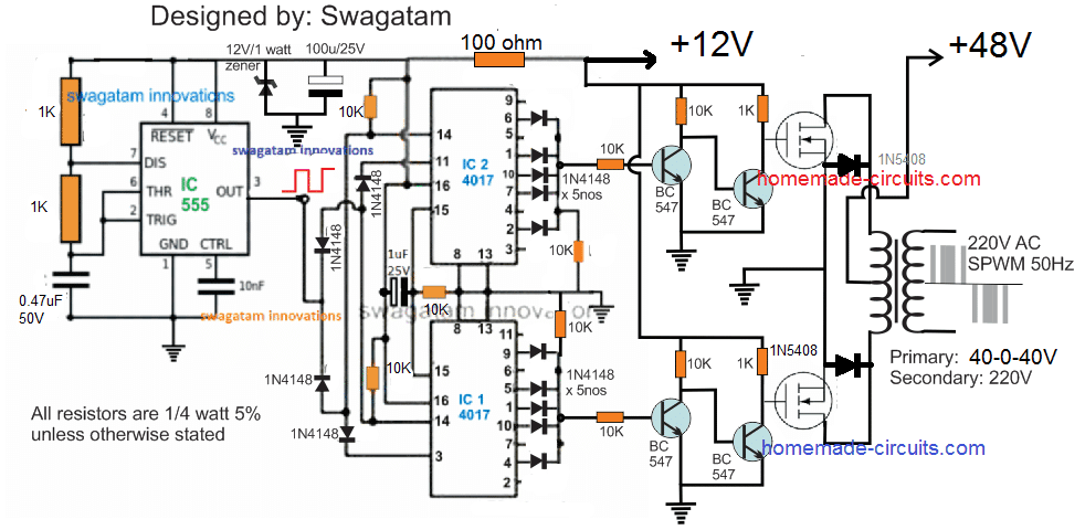
8 3 2020 The working of the Inverter can be understood from the following explanation Circuit Operation As can be seen two IC 4017 are cascaded to form an 18 pin sequencing logic circuit wherein the each negative pulse or frequency from the IC 555 produces a shifting output sequence across each of the indicated outputs of the two 4017 ICs starting from pin 9 of the upper IC upto

SG3524 PWM INVERTER CIRCUIT Many circuits Sumber : manycircuits.blogspot.com
PWM Inverter Circuit
PWM Pulse Width Modulation signal based inverters are produce output as pure sine wave and it can be used for any electric appliance that meets the inverter output range Simple and powerful PWM inverter circuit diagram designed with IC SG3524 Regulating Pulse Width Modulator gives upto 230V AC from 12V DC supply
Inverter sg3524, Ic SG3524N, Irfp250 inverter circuit,

Single phase PWM inverter Download Scientific Diagram Sumber : www.researchgate.net
PWM Inverter Using IC TL494 Circuit Homemade Circuit
8 3 2020 Here we discuss a versatile PWM based modified sine wave inverter circuit which incorporates the IC TL494 for the required advanced PWM processing Referring to the figure above the various pinout functions of the IC for implementing the PWM inverter operations may be understood with the following points Pinout Function of the IC TL494

250 to 5000 Watts PWM DC AC 220V Power Inverter Sumber : www.instructables.com
PWM Inverter Circuit Diagram using TL494
An inverter is a circuit that converts Direct Current DC to Alternating Current AC A PWM inverter is a type of circuit that uses modified square waves to simulate the effects of Alternating Current AC which is suitable for powering most of your household appliances I say most of because there generally exist two types of inverters the first type is the so called a modified square wave

SG3525 Pure Sinewave Inverter Circuit Sumber : www.homemade-circuits.com
PWM Pulse Width Modulation for DC Motor Speed and LED
Pulse Width Modulation PWM allows for electronic control over DC motor speed or LED brightness This articles features schematics and photos of circuits for making PWM without a microcontroller but instead uses a 74AC14 logic inverter chip diodes a capacitor and potentiometer
250W PWM inverter circuit SG3524 ELECTRONICSMASTER Sumber : electronicsmaster.weebly.com
PWM Inverter ElectroSchematics com
In order to increase the efficiency of the PWM inverter the electronic circuit is highly sophisticated with battery charge sensor AC mains sensor Soft start facility output control etc The PWM controller circuit uses PWM IC KA 3225 or LM 494 These ICs have internal circuits for the entire operation of the pulse width modulation
PWM inverter circuit based on SG3524 12V input 220V Sumber : www.circuitstoday.com
Introduction to PWM Inverters CircuitsToday
PWM controller circuit regulate the output voltage of the inverter Usually a single PWM IC such as KA3525 or LM494 are used for the purpose The entire circuits needed for the PWM operation will be incorporated in such ICs
PWM Inverter Circuit Sumber : theorycircuit.com
PWM inverter circuit based on SG3524 12V input 220V
250W PWM inverter circuit SG3524 A 250W PWM inverter circuit built around IC SG3524 is shown here SG3524 is an integrated switching regulator circuit that has all essential circuitry required for making a switching regulator in single ended or push pull mode

Inverter 5000 Watt PWM Circuit Schematic Electronics Sumber : circuitschematicelectronics.blogspot.com

PWM Inverter Using IC TL494 Circuit Homemade Circuit Sumber : www.homemade-circuits.com

PWM Inverter Using IC TL494 Circuit Homemade Circuit Sumber : www.homemade-circuits.com

PWM inverter circuit 500 Watt low cost Circuits DIY Sumber : www.circuitsdiy.com

PWM Sinewave 5kva Inverter Circuit Sumber : www.homemade-circuits.com


0 Comments